UVMapping Bases |
|||||
This is a presentation of mapping in max, Material ID and the materials Sub-Multi Object. How to assign several textures to an object, how to place the mapping coordinates, how to apply them, improve them and finally how to Unwrap the texture for use in a 2d paint package. |
|||||
|
|||||
To illustrate all this, we will use a simple cube with three divisions and some extruded faces as you can see opposite. |
 |
||||
  |
By default during its creation, an object does not have a true material, it just has a color chosen by chance.
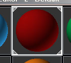
To apply a particular material we use the Material Editor. Material Editor is a relatively powerful editor. In top of the unused material slots (in gray) on which we come to apply and visualize materials. |
||||
 |
To apply just select a slot and change the color Ambient, Diffuse etc.
Make the same changes for the others slots opposite, just use different colors. To apply a material to the object, just select a Material as shown. Now Select your object then click on the Assign Material to Selection icon.  Note that the framework of the slot changes and 4 white bevels appear indicating that this material is currently assigned with an object in the scene. We can also Drag and Drop a material directly onto an object in the viewport to assign it. |
||||
  |
Select your red material and assign it to the object, note that bevels of blue material disappear because it is no longer assigned in the scene anymore. |
||||
How to apply several materials to the same object? For that we need to use sub-object mode. We work in Poly Edit or Mesh Edit mode using polygons or elements. Select the faces you want, choose another material and assign it. This time the material applies only to the selection. |
|||||
|
|||||
|
|||||
The object with 5 materials applied. Note that all 5 slots have their corners beveled. Deselect all the faces of the object then go back into object mode. |
|||||
  |
In Material Editor, select a free slot, click on the Get Material Icon, Select from Scene. This makes it possible to recover the Material applied to an object. Here we find ourselves with not a material of the Standard type as by default but one of the Multi/Sub-Object type. With this type of material we make it possible to apply several textures to an object. So you see we can create it as we did, by assigning Standard materials with a selection of faces.
|
||||
 |
Note that if we change a material in a slot, the Multi/Sub-Object material is also updated because they are dependent on each other (an Instance). |
||||
Before going further, let us clean the slots of Material Editor. For that we right click on a slot and in the menu which appears select 5x3 Samples. We now have more smaller slots. |
 |
||||
   |
Select the Original color slots and click on the Reset Map icon. A Dialogue Box appears, select Affect Only in Editor Slot because we do not wish to erase material already assigned with the object. This procedure makes it possible to release the slots for later use, and because we cannot see all 24 Material Editor Slots on screen at once we may from time to time wish to clear these slots. (3DSmax is not limited to 24 materials fortunately:)) Erase all the slots and find the material of the object, use the Get Material Icon, Select from Scene as we did previously. |
||||
 |
Name this material in the field designed for this purpose. |
  |
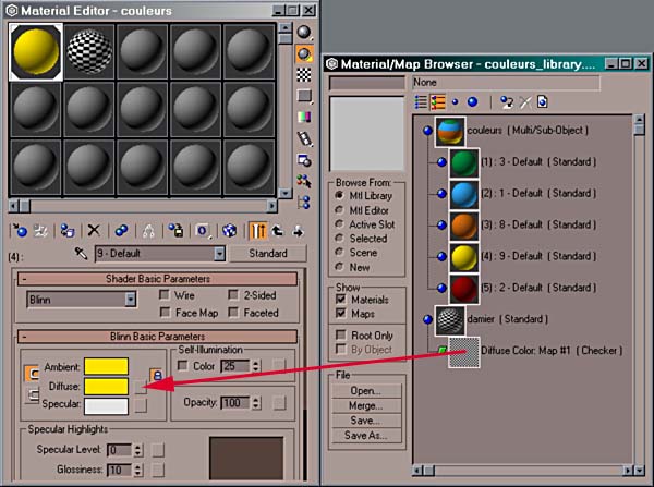
To manage an objects materials we should not be satisfied with the slots, they are just there to allow us to edit them. A further step is necessary to use the material libraries. A material library is a *.mat file, and in them we can record hundreds the materials. That makes it possible to constitute reusable material libraries from other *.max files. Click on the icon Get Material. The window Material Browser appears. |
||
  |
By default max saves a material library, into a 3dsmax.mat in the Matlibs directory.
To create your own library, within the framework use Browse From and select Scene. Only one material exists for the moment, it is the Colors material created previously. Select Scene in the Browse From: Palette then Click Save As, to save our working Scenes Mat file with a name of your choice.
It is good practice to associate a library with a project so as not to confuse its use with the other *.max files. Although we can still use these |
||||
 |
Select the Mtl Library. To charge your library Open your premade *Mat file. Note that we can amalgamate several libraries with Merge. |
||||
  |
Let us create another material in the slot on right-hand side. Click on the square opposite Diffuse.
|
||||
  |
Material/Map Browser appears, click Checker. Here we will use the procedural texture of checker. A procedural texture is a texture generated mathematically by max and avoids having to use a bitmap file for example. Within the Coordinates framework, change Tiling (repetition of the image) to 10 for both U and V. The checker now repeats 10 times on the object. |
||||
    |
Go up a level in Material Editor, by clicking the Go to Parent icon. This returns us to the top level of our material. Within the Maps framework, the Channels Diffuses Color has the Checker texture assigned. Name the material checker
|
||||
   |
To put this new material in our library, click on the Put to Library icon.
Max requires a new name, but we can leave the name as is, namely checker
|
||||
 |
By changing the view as shown opposite (uncheck the Root Only option) we can see the tree structure of our materials.
|
||||
 |
|||||
|
Return on Material Editor, select the "colors" slot material then click on the yellow Sub Material. Make a drag and drop of the Checker material from the Material/Map Browser on the framework opposite to the Diffuse map like above. That makes it possible to quickly copy a material to the Sub-Material of another slot. Repeat the same operation on the other Sub Materials. |
|||||
To move from one Sub Material to another, use the icon Go Forward. |
|||||
 |
Change the white color of each checker to the originals diffuse color.
Name each Sub-Material in the same way that you would a Standard Material. It should be noted that we can add another name in the Name column. |
||||
We will now apply mapping coordinates to the object.
The mapping coordinates indicate to max how a bitmap texture or 2d procedural (in this case Checker) is projected on an object. (a 3d procedural texture such as Noise do not need mapping coordinates because they are made from a calculation, a function in 3d space and are independent of the object itself). By default an object does not have mapping coordinates, it is necessary to define how to cover an object. In the case of a complex object such &as we have here we need several projections of these coordinates. |
  |
To assign mapping coordinates for each material, we select the corresponding faces. In Surface Properties Material, Mesh Edit or Poly Edit click on Select by ID. The Material ID is the number of the sub-material applied to the object. Here there are 5 Materials ID and the blue material has for Mat. ID 2. |
|||
Apply UVW Mapping. Why UVW? 3d uses XYZ for coordinates the objects, for the mapping coordinates UVW are used.
|
 |
||||
|
|||||
By default, Planer projection is that will work well as it is what we need here. Note the rectangle which appears in the viewport, it is the representation of the projection that the mapping coordinates use. |
|||||
  |
By default, max dimensions objects with the dimensions of the selection with planer mapping. We will set the same values in Length and Width to have a square projection. Indeed it is necessary to provide a square texture and if possible in the dimensions of 128x128 pixels, 256x256, 512x512 etc. For optimal use RAM it is preferable to use these dimensions. |
||||
  |
To see the texture applied in the viewport, activate the Show Map icon. This should be activated for each material applied. |
||||
|
|||||
The representation of this rectangle in mapping is called a Gizmo in max.
If we Edit in sub-object mode modifying UVW Mapping by selecting the Gizmo, this becomes The orientation of the mapping is given by the green feature for the axis of U and by the yellow segment for V, |
|||||
 |
Rotation the Gizmo on the Z axis. The texture follows this rotation. To cancel use Ctrl Z. Also while holding the Left Mouse Button if you tap the Right Mouse Button, this will Cancel your current edit. This works for all editing within max. |
||||
|
To continue mapping the object, for each Material ID select the corresponding faces then apply mapping coordinates. (also called UV to make it shorter). Apply the modifier Poly Select or Mesh Select according to the nature of the object. |
||||
|
Apply UVW Mapping. And change to Cylindrical Mapping. |
||||
Cylindrical Gizmo appears but it is out of proportion with the dimensions of the selection. |
 |
||||
|
|||||
 |
To set it to the right dimension, click on the FIT button. "Upper Left Pic" Apply the Orange faces with the Checker material. |
||||
As for the Gizmo, a green reference mark indicates were the mapping joins itself.
Nevertheless it is still this type of projection which will allow your mapping to conform quickly here. |
  |
||||
|
Correct the mapping coordinates with Mesh Edit or Poly Edit on a traditional object. Collapse the Stack. Ensure that the Object has Collapsed and apply Unwrap UVW. Click on Edit... |
||||
 |
|||||
The UV editor opens and the object lines appear.
These lines correspond to the mapping coordinates assigned with each face. |
 |
||||
To clean up the congested view of the material use the show map icon and instead of showing All ID' S, select the ID 3 corresponding with the orange checker that we want to view. All that remains is the UV assigned faces having the ID 3. |
|||||
  |
Now in sub-object mode select "Select Face". Go into the option Edit UVW while clicking on the Unwrap icon Options. To activate Constant Update and Show Selected Vertices. |
||||
|
|||||
Select the common points on the right, and in the viewport the corresponding vertices are also selected. Although projection is in 3 dimensions, we work in 2d on a UV plane. The goal being to obtain one UV plane unfolded without distorting the checker. Rather than working with the object in 3d, with the tools of traditional modeling, we move the mapping coordinates onto a 2d plane, which is simpler and faster. |
|||||
   |
We will make the same adjustments for the other points by watching the result in the viewport. |
||||
|
|||||
Drag select the next set of Horizontal points and move them cleaningup the texture as we go. |
|||||
|
|||||
Continue for each column. At some stage you will need to select the points from the other side. |
|||||
|
|||||
Even them all out to match the dimensions. |
|||||
|
|||||
Here we arrive at a delicate part of the object because it is not good enough to just move the points, it will be necessary to detach the UVs as we would detach the faces of an object then apply the mapping. |
|||||
You may get a different set of faces than the ones shown by the pictures to the right but the process is the same.
Select any faces that don't conform, as shown opposite in User View (always in UVW Unwrap : Select Face mode). Click on Planar Map, and select the faces to receive mapping according to the average of the normals. |
   |
||||
Make the same selection for each of the two faces at the ends, and one after the other apply a UV Map. |
  |
||||
   |
Open Edit UV and select the ID 3. We can see that the successive mappings are superimposed. To put them in order, select a point of the main piece of UV (a set) and by clicking several times on the Expand Selection icon, extend the selection automatically with all the UVs. Finally move the selection. |
||||
 |
The 3 other sets of UV that come from the mapping are superimposed. The gray square which appears in the center of the Edit UV screen represents the mapping of the Gizmo. The three maps preceding the Gizmo are dimensioned with the exact size of the selected faces. To separate them click once on a point and use the Expand Selection icon to recover the complete set. Move the set and repeat this operation as above to have the 3 pieces of UV. |
||||
  |
Depending on the faces you needed to manipulate you may need to do this next step.
Check that you weld the points between them in the viewport of the corresponding points.
|
||||
|
Use Scale non-uniform if required for the horizontal or vertical lines.
|
 |
Now that we have adjusted the UVs leave a nice map.
Your face sets may be different to the ones shown by the pictures to the left. |
||
 |
Collapse the Stack. With checker in ID 3 now correctly mapped on the object. Collapsing the Stack after each Unwrap is not needed but that frees up some resources and we can always improve the UV thereafter... |
||||
|
|||||
For the yellow checkerwork (Chechmate ID 4), select with Select ID then UVW Map in mapping Box.
In Unwrap UVW, one sees only one square, makes UV of it are superimposed. Click on a point then Extand Select. Move UV to separate it from the others. Repeat the operation jusquà what there is superimposed no more UV. |
  |
||||
 |
The checker is stretched we will regulate it later |
||||
   |
Make it the same as the green checker (ID 1).
|
||||
For the red checker, place a Planer map it. |
 |
||||
|
We now make a Full set of UVs from all 5 IDs with the whole UV rearranged. This board could then be used in photoshop to paint a full texture for our object. |
|||||
 |
In Object mode Select Unwrap.
|
||||
 |
Use Expand Select to put them in order. |
||||
Isolate Checker ID 4 and weld the UV vertices, viewing in the viewport will help you repair the orientation of the UV.
Remembering that if you select a point and nudge the Weld Threshold up. You should see its matching pair lightup, thus making it easier to lineup the sets as required. |
  |
||||
  |
Even everything out for Checker ID 1. |
||||
  |
Although we can move, scale etc. as we wish in the UV Editor, we need to make a flat base for the UVs so that those IDs contained in the square are in the center of the UV Editor window. The coordinates of the UVs must lie inside our gray Square. Beyond this the texture repeats on itself. Before we scale the set of UVs. Position them in the square so they are coherent in the UV Editor window, i.e. part of the object does not have a mapping too fine and another too large. Visualize the scale of the sets of UVs so that the whole of the checker has the same size. |
||||
  |
Then select all the pieces and uniform scale them to fit them in the large square. Just position the other sets in the remaining space. Now we Collapse the Stack for the last time. |
||||
Here the goal is to make a single board of texture, and thus make only one bitmap to texture the object. It is generally more practical to manage because there is only one bitmap file to handle. |
 |
Now we have a Multi/Sub-Object material that we want to map to the object that has only one texture. To clean the Checker ID, select the object in Sub-Object mode and enter 1 in the field ID. The object does not have any more that one Checker ID but it has the Multi/Sub-Object Material assigned. |
|||
   |
In object mode assign the checker material. Now we see that the material slot Multi/Sub-Object does not have any beveled corners, proving that it is not assigned to the scene any more. If you use Unwrap UVW, we see that it has only one Checker ID. Also note that changing the ID does not affect any UVs on the object, fortunately:) |
||||
Now we have to crate an of image of our UV. For that we can capture the UVs Editor screen but you are better of using a small plugin named Texporter as this does a much better job.
Texporter Web site. Place it in/Plugins Directory of 3DSmax. |
 |
||||
It can generate an image of the UV in any size requested, This is great for textures like 2048x1024 by ex:)
|
 |
||||
|
|||||
 |
The top left picture shows the default mode settings for Texporter with filled polygons according to the normals of the object. The pictures to the top right and opposite, show the adjustments needed for maximum visibility in Photoshop. Then open the file in Photoshop or any other 2d paint program and check the result by replacing the Checker material with the bitmap texture file. |
||||