Modeling of the sword |
|||||
|
|||||
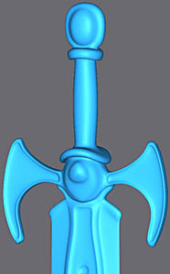
The sword is the occasion to show a new face of the polygonal subdivision on max 4.
The major part is devoted to modeling and towards the end you will see the new functions of Meshsmooth on max 4. As usual, to aid the modelling we use a drawing of the sword. One starts with a cylinder with 8 sides, make a rotation of 22.5° on the vertical axis so you have a line of polygons staright on in view Front. Apply a Mesh EDit and XForm to initialize the position of the object after rotation. |
|||||
|
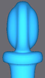
Extrude the face top then select the new faces faces for a second extrusion ( use local mode of Extrudes as with all Extrude of this tutorial).
Select the faces of the edge. |
||||
|
|||||
Apply a bend modifier. Choise the X axis and by modifying the angle deform the faces like above in the picture. Select the central polygon and scale - non uniform on axis Y |
|||||
|
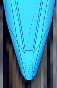
Extrude this polygon like opposite. Adjust the profile by scaling non uniform on X. |
||||
|
|||||
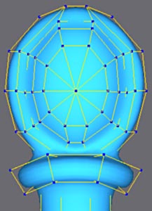
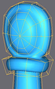
At the top, turn the edges and weld the vertex of the center to obtain the poly mesh as opposite. |
 |
||||
   |
|||||
Adjust the vertexes to finish the round-off. Select the vertexes of the center and scale non uniform to make the faces as shown |
|||||
Select the faces as in the picture and then extrude followed by Bevel like opposite.
|
  |
||||
  |
|||||
Adjust the vertexes like opposite by scaling non uniform on axis X and by Moveing on Y.
Select the faces of the center and apply Make Planar to make them plane. |
|||||
  |
|||||

Extrude these faces and form the round-off with Bevel. Insert a vertex as in the picture in the edge with Divide after having activated the 3d Snap in Midpoint mode (below). |
|||||
|
|||||
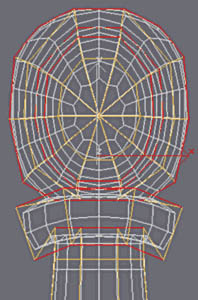
Turn on make visible edges like above. Adjust with a non uniform scale the vertexes top and center. |
|||||
   |
|||||
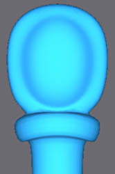
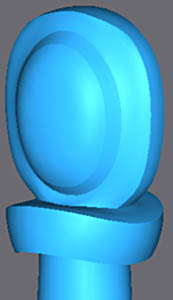
Apply Meshsmooth and as with the preceding sections, you can now adjust the low cage definition and view the high poly version. Once adjusted remove Meshsmooth and return to the low poly. |
|||||
|
Select the handle's edges and then Chamfer.
Move the two new edges as shown on the right. |
||||
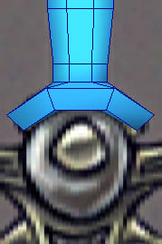
for the top, Extrude and tighten the faces with Bend. |
 |
||||
 |
Select the polygon as in the picture and flatten it with a non uniform scale set to the axis Y. |
||||
   |
|||||
 |
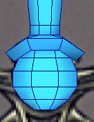
As in the preceding page, simplify the mesh at the end, round and scale the vertexes to obtain the result opposite. |
||||
|
|||||
Make a non-uniform scale to ajust the dimensions of section indicated |
|||||
   |
|||||
Extrude the faces as in the picture and finish with Bevel. |
|||||
  |
|||||
Extrude the faces and Bevel again, adjust the vertexes to obtain the result above (scale non uniform on X and Move on Y). |
|||||
  |
|||||
Aim for the dimensions above.
Extrude the central polygon. Insert a vertex and make the edges visible as on the last page. |
 |
||||
 |
Aim for the dimensions shown after scale non uniform on Y of the central vertexes. |
||||
|
|||||
Extrude the faces simultaneously. |
|||||
 |
Continue in the same way to make the following ones.
Use non-uniform Scale on X to position the vertexes horizontally and Move Y for the vertical. |
||||
|
|||||
Finish extrusions like above. |
|||||
|
|||||
Select the faces as in the picture and make one Extrude and Bevel, then repeat with a negative Extrude/Bevel to make the hollow.
To do one Extrudes without the news face not moving it is enough to move frankly vis-a-vis extrusion then totaling zero with the roll up of adjustment of extrusion. Then Bevel makes it possible to decrease the size of the extruded face, one thus creates a setback or an edge. |
|||||
|
|||||
Select the faces of the lower part, then Extrude/Bevel as shown above left and then repeat as in above right picture |
|||||
 |
Make any minor final necessary ajustments. |
||||
|
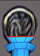
Then Extrude the main body of the blade.
Adjust on X with scale non-uniform. |
||||
|
|||||
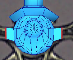
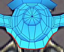
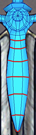
Select the faces in red and ajust the dimensions using a scale non-uniform on the y axis. |
|||||
|
|||||
Adjust the vertexes like above.
Insert a vertex into the edge as shown with the 3d Snap on set to Midpoint, hide the 2 edges and make visible the 2 others. Select the faces as in the picture and then follow a series of Extrude/Bevel to create the edge and another for the hollow. |
 |
||||
   |
|||||
On the point, make the horizontal edge like above.
Then move the vertexes downwards. Lastly, make visible the 2 edges like opposite. |
 |
||||
|
|||||
For drillings, select a quad as shown, use Extrude/Bevel and adjust the vertexes to have a square.
Extrude again into negative for the hole. Start again for the second hole. Finally remove the horizontal edges. That gives a better smoothing with Meshsmooth in this case. |
|||||
|
|||||
For the blade, always Extrude/Bevel as shown
Extrude the faces to build the blade. |
|||||
|
|||||
Adjust the vertexes on the top of the blade as shown above and continue to align the others perfectly |
|||||
|
|||||
When it come so the point of the support of the blade. select the vertexes in red and made a scale non-uniform on the axis Y.
|
|||||
|
Ajust the vertices on the y axis to obtain the horizontal row
Then extrude the remainder of the blade and use scales non-uniforms for the point. |
||||
  |
|||||
Adjust the edges at the point of the support of the blade to obtain the structure above. |
|||||
|
|||||
 |
The blade needs a hollow.
For this we use a series of Cuts with the 3DSnap Midpoint activated (top left). Simplify the point by welding the vertices as shown top right. |
||||
To form the furrow, select the central edges of both sides and make a scale non-uniform on the axis Y to get the right dimensions. |
 |
||||
  |
Pull down the vertex from the end of the furrow like opposite.
Insert a vertex with Divide and make additional edges as shown. |
||||
   |
|||||
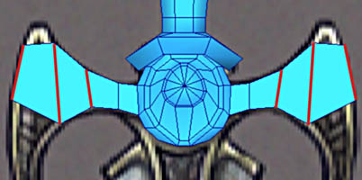
Finally to finish, on the top of the blade, make the diagonal edges visible and use a scale non-uniform on the vertexes of the edge of the blade to refine it. Note that the top is not thinned. |
|||||
  |
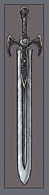
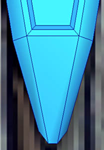
Modeling finished.
Smooth with meshsmooth, Nurms mode, iteration 2. Click on the images for bigger versions |
||||
Max 4 introduced the possibility of modifying the smoothing of the object with different values for separate vertices.
That in particular makes it possible to create edges more or less sharp, to locally decrease or increase the radius of curvature of smoothing. Subobject Level makes it possible to choise if you work with the vertexes or the edges. Control Level makes it possible to choose its level of influence, namely 0 for the grid equivalent to the low poly (here in this tutorial one limits oneself to this level), 1 with the mesh resulting from an iteration 1, 2 of the mesh of an iteration 2 etc. Of course you can also move the vertexes or edges but it should be better done on the low poly mesh Crease and weight functions in Edge and Vertex mode makes it possible to indicate the level of distorsion of the selection. |
 |
||||
 |
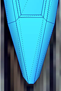
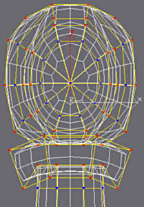
When one clicks on Edge or Vertex (while activating in this case Display Mesh Control) a low poly cage appears over the subdivided mesh. | ||||
  |
Continue in Edge mode and select like opposite.
In the Crease field enter value 0.5. In iteration 2 one sees the result clearly. That resembles the use of Smoothing Groups for smoothing but it is less brutal, the edges are not confused with the low poly mesh as with Smoothing Groups. |
||||
Following this test you may now reset the deformations by clicking reset edge weights
This panel allows you to rest the influences without having with all to start again... |
 |
||||
  |
In vertex mode select the vertexes as opposite and enter value 20 the Weight field.
This time not of edge but the curve of smoothing is modified according to the attractile vertexes. That makes it possible to avoid adding edges with chamferings for example to harden smoothing, and thus limiting the number of faces in the sudivided mesh. |
||||
Another point of interest for the later texturing stages, as you will see that more in detail in part 4 but it should be known that if one puts the co-ordinates of textures on the low poly mesh and then makes the subdivision with of Crease, Weight etc, those are absolutely not deformed. It is thus very practical because it is much easier to put co-ordinates and to improve them on a low poly mesh...
All that will be detailed in part 4. |
|||||
It should be noted that the low poly mesh should not re-edited when you have started to ajust the Crease or the Vertexes in the meshsmooth modifier. The edtion of Meshsmooth is thus to be added to a finished a completed object. |
|||||
|
|||||
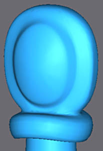
The finished sword on meshsmooth iteration 2. Here I gave only one dimensioned an angular crease. >By way of comparison the last image presents the sword with Meshsmooth by default. |
|||||
This technique of ajusting the subdivided object will be used for the remainder of the accessories, in particular the armour. That simplifies the ajusting and saves polygons for the final object. |
|||||