Assembly |
||||
|
||||
This is a delicate part, of the assembly ear+head.
Merge the ear in the scene with the head. |
 |
|||
|
||||
Hide the head. For right-hand side, (looking into the ear as shown) remove the 2 triangles of the previously extruded parts . Make visible the diagonal edges. |
||||
|
||||
 |
Select the internal edges of the ear and extrude with shift+scale.
|
|||
 |
Align the ear compared to cranium. |
|||
|
||||
|
Select the ear and view its Properties (right click) and Trun off BackFaces Culling. That makes it possible to see the faces whose normals are not directed towards the observer. Select the head, activate 3d Snap in vertex mode and with Create Vertex, create the vertexes for the head in the same arrangement as the ear ones (as shown) |
 |
|||
|
||||
With the new vertices ready in the head you can now hide the ear as these are enough to build the faces that form the of junction of the head to the ear. As usual, make as many quads as you can.
Adjust the vertexes around the edge to give a more regular form. |
||||
|
||||
Place the ear so to allign the pairs of vertices on head/ear as close as possible.
Select the head and then Attach. (check that you have Editable Mesh in the pile of both objects, if necessary, remove a Meshsmooth and colapse the stack). Select the vertexes pairs and then weld them together. The ear and the head should now be one with no gaps or holes in this area. Make any final adjustments of these welded verticies to harmonize the curves of the ear-head join. |
||||


|
|||
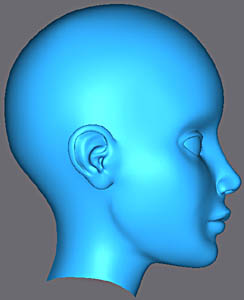
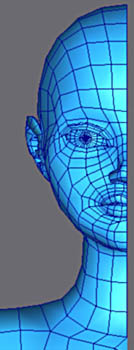
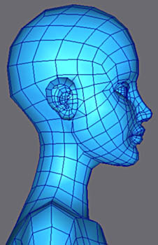
The look of the final low poly cage.
It is this low polygon mesh that you preserves for the next parts. Click on the images to see them large. |
 |
||
|
|||
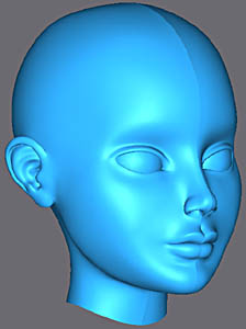
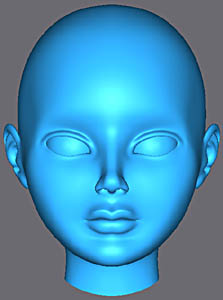
Subdivision in iteration 2.
Click on the images to see them large. |
 |
||
The next part will be devoted to the modeling of the accessories (clothes, sword, but also the hair and eyes). |
|||
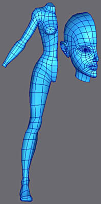 |
To assemble the body, merge the head and the eye in the bodys scene.
Remove Meshsmooth from the stacks of both objects and keep only Editable Mesh. |
||
 |
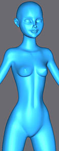
Using the background image as a guide scale the body with a uniform scale. |
||
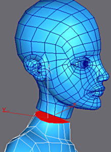 |
On the body, erase the polygon in the middle of the neck.
Then with the Attach button, click on the head to make one object. |
||
 |
With Create, build the faces to connect the head to the body.
As it happens there is the same number of vertexes in top and in bottom thus one has only quadrangles with the final mesh at this join :) |
||
|
|||
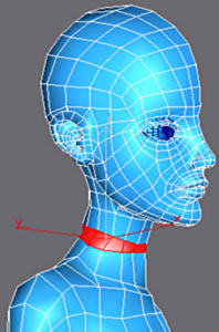
Finally adjust the vertexes of the neck to give a regular form. |
|||
|
|||
To make sure that the vertexes are placed on the bodys axis of symmetry and so all aligned vertically, select them then selectnon uniform scale and then right click on the icon to open the 'transform type-in' enter 0 in the field of the x axis.
All these vertexes are now perfectly on the same vertical axis. |
 |
||
|
|||
Select all the objects and in the Hierarchy panel, select Pivot, Affect Only Pivot and click on 'Center to Object'.
That makes it possible to center the pivots of the objects in their geometrical center. Indeed until now the body and the head had kept the pivot of the initial starting object It is easier to move the right part of the character after the copy to mirror in Copy mode |
|||

|
Select the left part and with Attach activated, click on the right part.
Select the vertexes of the body's axis of symmetry To weld the two parts it is enough to apply Weld with a low value. This value indicates a distance to which vertexes within this value become welded together. To be sure to weld the vertexes in their pairs check that the number of selected vertecies after Weld is half of those initially selected. If it is not the case, decrease the tolerance of Weld etc... |
||||
 |
Here, max indicated 166 vertexes before Weld and 83 after thus they were welded in their pairs as desired... |
||||
|
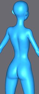
|||||
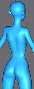
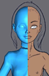
| Check visually that they are all correctly welded by looking at the model in low poly. Then apply a Meshsmooth modifier. Click on the images to see them large. |
|||||
| As usual, preserve the low poly model for the next parts (dont collapse!) | |||||